
A little room to wonder
Electrical Circuits
Distinguish charge flow, potential difference and resistance using safe paper circuit models.
What changes when a circuit offers one path or several paths?
A circuit is a connected system
In a simple steady circuit, electric charge flows around a closed conducting path. Current measures the rate of charge flow, in amperes. Potential difference, often called voltage, describes energy transferred per unit charge between two points. These are different quantities: a large voltage does not by itself tell you the current.
Resistance describes the relationship between voltage across a component and current through it. For an ideal ohmic resistor at fixed conditions, V = IR. A circuit diagram uses agreed symbols to show connections rather than the physical appearance or position of each component.
Calculate a stated model
Consider a fictional ideal 6-volt source connected to a 3-ohm resistor. The model gives I = V ÷ R = 6 ÷ 3 = 2 amperes. Adding another 3-ohm resistor in series gives a total of 6 ohms and a current of 1 ampere. The numbers illustrate reasoning; they are not a specification for building a circuit.
The series path has no branch, so the same steady current passes through both resistors. Charge is not consumed by the first resistor and replaced later. Energy is transferred as charge moves through the circuit; current and energy should not be used as interchangeable words.
Branches change the connections
In a parallel arrangement, components connect across the same two nodes. Each branch has the same potential difference between those nodes, while branch currents can differ. The total current at a junction equals the sum of the outgoing branch currents in this steady model.
For two ideal 6-ohm resistors in parallel across 6 volts, each branch carries 1 ampere, making 2 amperes in total. Drawing the nodes first helps you identify the arrangement. Components that sit next to each other in a photograph are not necessarily connected in parallel.
Respect the model’s boundaries
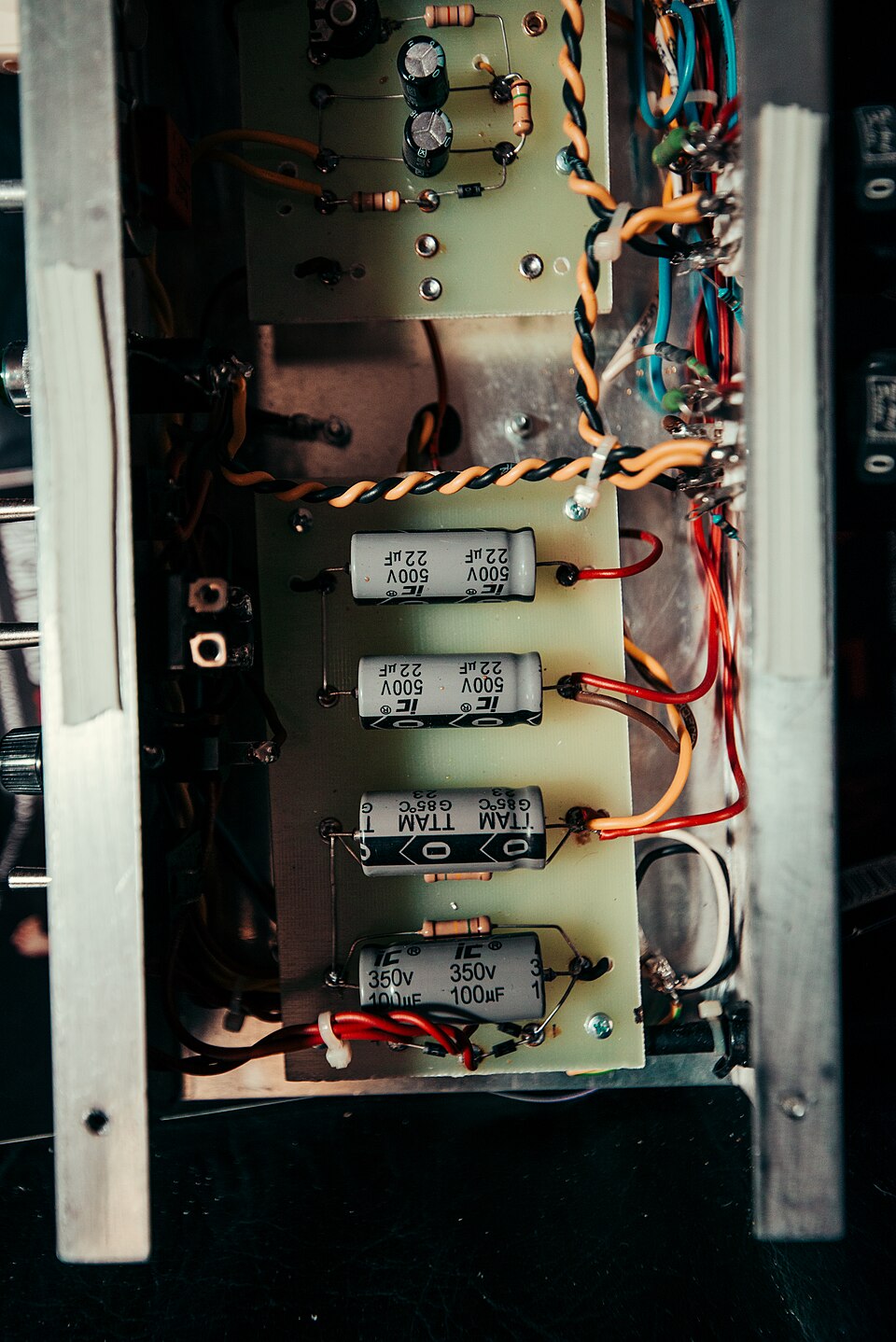
Real sources, wires and components have limits, and some components do not follow a constant-resistance model. A photo of a circuit board cannot reveal all connections or prove that a device is safe. Paper diagrams let you investigate relationships without opening equipment or experimenting with power sources.
Only if you feel like trying
Compare two paper circuits
- Draw a source and two labelled ideal resistors in one series path.
- Redraw the resistors across the same two nodes in parallel.
- Use the fictional examples above to label currents, then state one assumption in each calculation.
Paper only. Do not connect batteries, sockets, chargers or unknown components, and do not open electrical equipment.
Look at the sources.
These references informed this introduction. You can check who published them, what evidence they use and whether you would ask another question.
- OpenStax, Rice UniversitySeries Circuits
- OpenStax, Rice UniversityParallel Circuits
Research checked 1 November 2026. External pages have their own content and privacy practices.
Where could this connect?
These are editorial links between subjects. You choose which, if any, to follow.
Energy & Power
A circuit transfers energy, while current measures charge flow rather than energy itself.
Follow this connection
Engineering
Component choices and connections determine how an electrical system behaves.
Follow this connectionPatterns & Algebra
Substitution and rearranging relationships make circuit calculations understandable.
Follow this connection