A little room to wonder
Structures & Bridges
Trace how a structure carries a load, then distinguish a useful small model from evidence about a real bridge.
Where does a load go after it reaches a bridge deck?
A structure provides a load path
A load is a force acting on a structure: its own weight, for example, or the weight of something it supports. The deck of a bridge passes forces through other parts towards its supports and the ground. Following that route is called thinking about a load path. A good drawing labels the supports and connections as well as the span between them.
Tension pulls a member; compression pushes it. Members can also bend, and connections matter. Calling an entire bridge “in compression” hides the different jobs of its parts. Which parts carry which forces depends on the arrangement and the loading.
Why a diagonal can matter
In an ideal model with freely pivoting joints, a four-sided frame can change shape without changing the lengths of its sides. Adding a diagonal divides it into triangles and constrains that movement. Real frames have material stiffness and joints with their own behaviour, so this geometric explanation is a starting model, not a complete strength calculation.
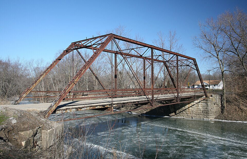
A truss uses connected members in a repeated arrangement, often including triangles. In a simplified truss analysis, forces act at joints and members carry tension or compression. A photograph cannot establish whether those modelling assumptions fit a particular structure.
Work through a comparison
In a fictional paper-span test, the same sheet spans a 10-centimetre gap. Flat paper sags 12 millimetres at the centre; a folded version sags 4 millimetres under its own weight. The difference is 8 millimetres. The fold changed the arrangement of the material while the sheet and gap stayed the same.
This supports a narrow statement about these two models under this setup. It does not establish a maximum safe load or explain every cause of the difference. Repeated trials, consistent measurement positions and notes about the supports would strengthen the comparison.
Strength is not just a shape
A triangle is not a guarantee of safety. Material quality, connections, foundations, movement and maintenance all affect a real structure. A model can help you ask a better question while leaving many of those factors out. State the question it answers, then name a question it cannot answer.
Only if you feel like trying
Draw two load paths
- Draw a fictional beam bridge and label deck, supports and ground.
- Add arrows showing where a downward load could be transferred. Mark arrows as a simplified model.
- Draw a truss alternative and identify a connection whose behaviour you would need to investigate.
Optional paper activity. Do not climb, load-test or alter a real structure; no construction is needed.
Look at the sources.
These references informed this introduction. You can check who published them, what evidence they use and whether you would ask another question.
- TeachEngineering, University of Colorado BoulderBridge Types: Tensile & Compressive Forces
- TeachEngineering, University of Colorado BoulderDoing the Math: Analysis of Forces in a Truss Bridge
Research checked 1 November 2026. External pages have their own content and privacy practices.
Where could this connect?
These are editorial links between subjects. You choose which, if any, to follow.
Engineering
Purpose, constraints and evidence guide the design of a structure.
Follow this connection
Forces & Motion
Forces and equilibrium explain why a load must be balanced by other forces.
Follow this connectionGeometry & Symmetry
Geometric constraints help explain how bracing changes a frame’s possible movement.
Follow this connection