
Engineering · Investigate
Explain an invented mechanism
How can a sequence of labelled drawings show where motion goes?
Trace the input and output of a fictional two-gear display without building a machine.
10–20 minutes, or one small comparison for a first try. More time is optional.
Start here
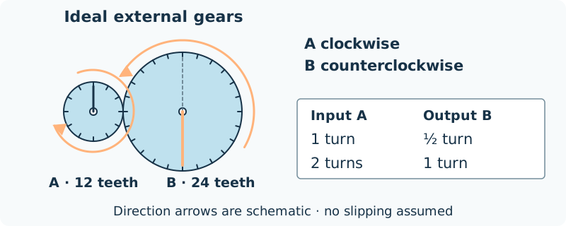
Draw two touching circles. Label the smaller input A: 12 teeth, and the larger output B: 24 teeth.
Use your idea or the example below. Talk, write, draw, point or listen first. You can stop after one step.
Try it your way.
Name the input
Choose which gear a fictional handle turns. Mark A with an arrow; this example uses clockwise input.
Follow the contact
For two external gears that mesh without slipping, the second turns in the opposite direction. Mark B counterclockwise.
Track a turn
One turn of A passes 12 teeth through the contact. That moves 12 of B’s 24 teeth: half a turn. Show the same starting mark on a second sketch.
Explain the model
Add an input-to-output caption. Keep your explanation to direction and turns; the sketch does not prove a real mechanism will work.
One possible version
Original model: a rotating sign
These are ideal external gears in an invented desk-display drawing, not tested hardware.
- A has 12 teeth; B has 24. Their sizes and tooth counts stay fixed.
- A turns clockwise once; B turns counterclockwise half a turn.
- Two turns of A would move B through one complete turn.
The model assumes gears mesh without slipping. It does not calculate friction, strength or the force needed.
Something to keep?
Which claim follows from the tooth counts, and which claim would require a real test?
You can keep a question, a sketch or a change of mind. A finished product is optional.
This opens an editable starter in your project tools. It asks before replacing open work. Choosing it does not save or share your work automatically.